Strong foundations make strong structures, with hidden footings doing the critical work of supporting everything above.
Careful planning, thorough geotechnical investigation, and informed design decisions ensure that the footing system not only supports the structure, but also protects the investment and reduces long-term maintenance costs.
Impact Structural Engineers Director, Matt Gorring is a firm believer in this principle, championing the importance of foundational excellence in Fibre Reinforced Polymer (FRP) projects.
“Every structure is only as good as the foundations it sits on. A well-designed footing system provides solid support, prevents settlement or differential movement and resists against reactive soil,” Matt Gorring said.
“If the footings are poorly designed, it doesn’t matter how strong or durable the structure is, over time, you may get movement, long-term damage or potentially even a critical failure,” Mr Gorring said.
“The key message here is simple. Bad footing design makes a bad structure and getting this part right is what protects the investment and ensures the performance of the structure well into the future,” he said.
‘The first step to a well-designed footing system is the geotechnical investigation report.”
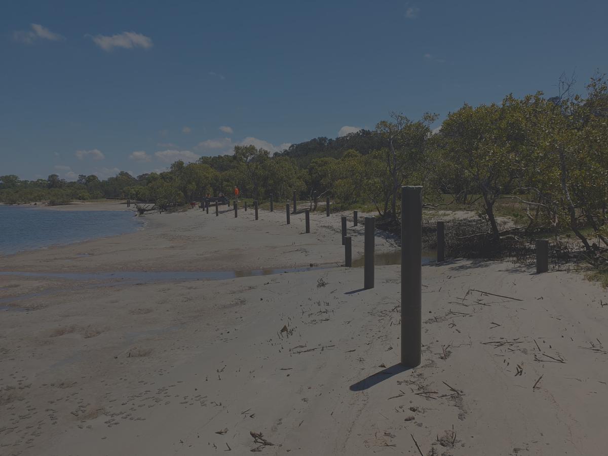
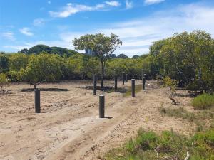
 Pictured – Driven FRP piles for a boardwalk structure.
Before any construction begins, understanding what lies beneath the surface is critical.
“A geotech report gives us the soil profile and key parameters we need to design the footings,” Matt Gorring said.
“These are absolutely essential for each project location which has unique ground conditions that vary significantly from site to site,” Mr Gorring said.
“Investing in good quality geotech information and a study might feel like extra cost at the start, but it always pays off,” he said.
“Better data leads to more efficient design, less material use and reduced long-term issues such as damage and ongoing movement.”
“Investing in a quality geotechnical report almost always saves money and headaches in the long run.”
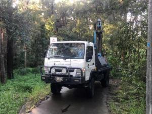 Pictured – Wagner Soil Testing at a geotechnical report location.
When it comes to understanding a site’s ground conditions, the first step is pinpointing exactly what’s beneath the surface.
“The site plan borehole location is the first point of call. It tells us what the soil profile is at certain locations at the site in relation to where the proposed structure or footings are going to be constructed,” Matt Gorring said.
“The soil profile is usually in the form of bore logs or subsurface summaries which will give us an overview of the soil profile at these different locations where the boreholes are taken, usually including descriptions of the material and consistencies,” Mr Gorring said.
“The reactivity or the site classification will give us an indication of the potential of the soil for shrinking and swelling with variations in moisture content usually classed on severity of reactivity in accordance with AS2870 which is the residential slab and footing standard, ” he said.
“We will also look at the soil properties. This tells us a little bit more about the inherent properties of each layer such as the unit weight which will give us an idea of the density of the material, friction angle and cohesion.”
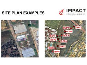 Pictured – Site plan examples including borehole locations.
With the ground conditions understood, the next step is turning that data into practical design decisions.
“The geotechnical engineer’s recommendations for the footings are usually looked at to get some recommendations from the geotechnical engineer themselves as to what a suitable footing system might be and take that into account,” Matt Gorring said.
“The design parameters are typically used for designing the footings themselves provided in kPa factored as ultimate or allowable to suit different load cases,” Mr Gorring said.
“We also have a look at how the soil has a potential to settle over time under expected service loads,” he said.
“And then constructability advice for excavatability, access issues and expected equipment for constructing the footing system.”
“We take all this into account and it all shapes every decision we make about specifying the footing system. It’s absolutely invaluable getting that from the geotech information.”
“The final choice depends on the particular soil profile, site constraints, and constructability.”
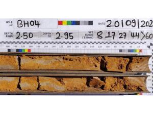 Pictured – Soil profile information obtained from a borehole.
When it comes to footing systems, conventional reinforced concrete offers a proven and adaptable solution.
“Conventional reinforced concrete systems are well understood, widely used and a good benchmark to compare other systems against,” Matt Gorring said.
“Deep systems usually consist of bored piers or sometimes CFA piles which are a variant where the concrete is pumped while the auger is withdrawn to avoid leaving open excavations,” Mr Gorring said.
“Then we’ve got shallow systems which usually consist of pad and strip footings. Everyone’s somewhat familiar with these if you’ve been involved in construction projects,” he said.
“The advantage of these is pretty much that it’s a proven construction method. So you’ve got familiarity of the design and construction with engineers and contractors; it’s generally a reliable, stable support system if designed correctly.”
“It’s versatile across a wide range of soil conditions because you can employ deep or shallow systems depending on the specific site.”
“Concrete footings are also reasonably durable with a design life of roughly 50 years. Construction is typically straightforward using readily available equipment, and materials are usually cost-effective and easy to source.”
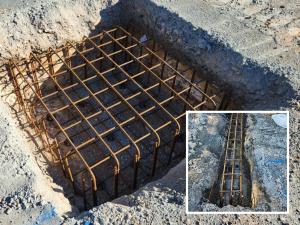
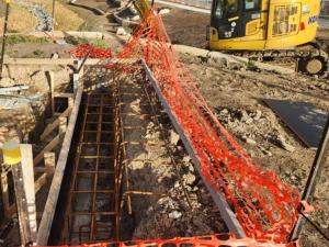 Pictured – A conventional reinforced concrete footing system.
Shallow footings are a common and reliable option, designed around basic principles.
“Shallow footings are generally less than a meter deep and they are used when soils near the surface are strong and uniform. These are pad and strip footings,” Matt Gorring said.
“Vertically they work by spreading the load over an area large enough that the soil can safely resist that load, using the bearing pressure of the soil beneath,” Mr Gorring said.
“For a downward axial load, we have the bearing capacity of the soil resisting the downward load multiplied by the area of the pad or strip,” he said.
“Similarly for an uplift vertical load – typically we will take into consideration the self-weight of the concrete only, and neglect any friction contact with the soil due to the footing usually being quite shallow.”
“For horizontal loads and overturning moments, we usually use self-weight of the footing, frictional resistance at the base and passive earth pressure which is basically the soil pushing against the side of the footing when horizontal load is applied.”
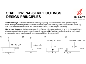 Pictured – Shallow pad/strip footings design principles.
Footing reinforcement usually follows standard code requirements.
“In terms of reinforcement detailing, the reinforcement is usually governed by minimum requirements in AS3600, the concrete structures code,” Matt Gorring said.
“Sometimes if there are particular requirements for strength such as a spanning beam between piers or a very highly loaded pad where you have to check the strength capacity of the footing, we might design the footing based on conventional structural analysis with reinforced concrete capacities,” Mr Gorring said.
“Sometimes if there is a super reactive site as well, you might put extra reinforcement in just to protect against that high reactivity,” he said.
“But usually it’s just minimum requirements.”
 Pictured – Shallow pad and strip footing systems.
When surface soils can’t provide enough support, deep footings are a smart choice.
“Deep footings are used when the surface soils are weak or variable or we need more resistance to the vertical and horizontal load cases, bored piers being the main option,” Matt Gorring said.
“These extend down to reach stronger layers and transfer vertical load through a combination of the end bearing resistance plus skin friction – which is basically when the soil grips the pole shaft,” Mr Gorring said.
“For the downward axial load, you get the base bearing pressure times the base area similar to the pad footing but in this case we have a circular bored pier so we do our pi calculations to get the area,” he said.
“So we do our pie calculations to get the area and then the skin friction. We also get additional skin friction resistance by getting into these deep soils – which is when the soil provides frictional grip on the side of the pier to resist vertical loads.”
“For the uplift case, we still have the self-weight but again we get that skin friction grip preventing the footing from wanting to rip out of the ground. The skin friction component is calculated with the pressure capacity in kPa obtained from the geotech report, multiplied by the shaft surface area.”
“Horizontally, we design them based on how the soil deflects laterally based on its stiffness and look at the subgrade reaction behaviour to ensure that the ultimate horizontal stresses are within limits for the particular soil type.”
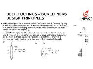 Pictured – Deep footings – bored piers design principles.
Deep footing reinforcement also typically follows standard code requirements.
“Reinforcement detailing for deep footings are again usually governed by minimum reinforcement requirements coming from AS2159 which is the piling code,” Matt Gorring said.
“Sometimes if you’ve got a very highly loaded pile or particularly high horizontal forces, you might do a check for the moment capacity and ensure that your bored pier has enough strength,” Mr Gorring said.
“A lot of the software, like a p-y curve analysis software actually provides the bending moment as an output,” he said.
“So it’s a pretty easy check by traditional reinforced concrete analysis and usually it’s that minimum reinforcement that is going to govern in a lot of cases.”
“If you do happen to have a post cast into the footing, you can sometimes get away with not providing any additional reinforcement because the post will engage the concrete, providing a nominal bearing capacity to the section without any additional reinforcement.”
 Pictured – A steel post that can be cast into a deep footing.
An alternative to traditional concrete footing systems is driven FRP piles.
“Instead of pouring the concrete, we drive the FRP sections directly into the ground and that becomes the footing,” Matt Gorring said.
“The suitable soil profiles for easy driving conditions are softer clays or sands, without any rock or hard soil layers because these can cause issues with the installation,” Mr Gorring said.
“In terms of design, the vertical capacity comes from the skin friction and the base bearing. It’s very similar to bored piers,” he said.
“This time we don’t really have the self-weight of the concrete to help resist against the uplift so we need to pay closer attention to the skin friction component for any upward loads.”
“The horizontal behaviour can be modelled in a similar p-y analysis software that accounts for the stiffness and the properties of the different soil layers.”
“It just gives us a really accurate picture of exactly how the pile is behaving and provides the outputs for deflection, internal pile forces and soil stresses.”
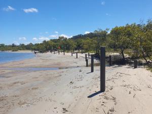
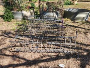
 Pictured – FRP piles that have been driven into the ground for a boardwalk project.
Driven FRP piles allow fast installation and real-time capacity checks.
“Installation is fast with piles being driven using drop hammers, vibratory rigs or somewhere in between such as a hydraulic impact driver,” Matt Gorring said.
“There’s no excavation, there’s no spoil and there’s no concrete curing or reinforcement,” Mr Gorring said.
“One of the big advantages of these driven piles is what happens during installation,” he said.
“When the pile is driven, the surrounding soil is compacted and densified, which increases the soil’s sheer strength and thus the skin friction grip on the pile which means that the actual load capacity is often higher than what we would predict from raw geotechnical parameters.”
“The key benefit here is in the direct on-site capacity verification where the true capacity is captured.”
“We measure the pile deflection under a certain hammer weight and drop height and then we use the Hiley formula which is an accepted method for converting this information into an actual capacity in kN based on the soil resistance.”
“So instead of relying on purely theoretical and conservative assumptions found in the geotech report like we might do for conventional concrete footings, we can confirm the real improved performance of the footing which gives us more confidence and often results in more efficient and cost effective designs.”
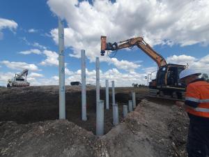 Pictured – FRP piles being driven by an impact hammer.
Benefits of driven FRP piles range from improved efficiency and durability to cost savings and sustainability.
“The advantages of driven FRP piles are certainly worth consideration,” Matt Gorring said.
“They offer exceptional durability. No corrosion, rot or concrete cancer which is especially critical in exterior or near coastal environments,” Mr Gorring said.
“They also make construction faster and simpler. There’s no need for excavation or concrete curing, and the piles achieve immediate load capacity once driven,” he said.
“In terms of material efficiency, you’re using fewer raw materials, lighter sections, and smaller machinery, which also reduces transport and handling requirements.”
“They’re also cost-effective as you avoid large concrete volumes, steel reinforcement, and spoil removal.”
“Finally, they deliver real sustainability benefits. Long-term maintenance savings, extended design life, and lower embodied energy of the footing system.”
“Overall, for suitable sites, these can be a vastly more efficient footing system from many different angles, as well as a more durable long-term solution.”
Watch the full webinar ‘Footing Fundamentals for FRP Structures’ featuring Impact Structural Engineers, Matt Gorring – https://www.youtube.com/watch?v=TxoGxM5q74Y&t=2308s
Read ‘Driving progress: Wagners FRP profiles redefine piling’ for more information on driven FRP piles – https://www.wagnerscft.com.au/driving-progress-wagners-frp-profiles-redefine-piling/
Have a question about footing systems or FRP piles? Complete the ‘Contact Us’ form or reach out to your local Wagners CFT Business Development Manager – https://www.wagnerscft.com.au/contact-us/